
How to Choose the Best Analog Splitter 4 20mA?
Choosing an Analog Splitter 4 20ma is not merely a matter of matching terminals. It affects signal accuracy, loop stability, maintenance time, and the quality of decisions made from field data. In a typical cabinet, one transmitter may feed a PLC, recorder, and control valve. Each device can introduce its own load, noise, or grounding problem.
The market is becoming less forgiving. MarketsandMarkets’ Industrial Automation Market report identifies continued investment in connected control systems and process instrumentation. ARC Advisory Group’s research on industrial automation also highlights the growing importance of reliable signal integration across distributed systems. These trends make signal conditioning a practical engineering decision, not an accessory purchase.
A strong selection begins with the application. Check input and output ranges, loop-powered or externally powered operation, isolation voltage, accuracy, response time, and terminal capacity. A 250-ohm receiver may work well, while several receivers can exceed the transmitter’s compliance voltage. That detail is easy to miss. It causes unstable readings.
NAMUR NE 43 can help define fault-current behavior. IEC 60381-1 provides an important reference for analog signal transmission. HART compatibility may also matter when technicians need device diagnostics without removing the splitter. Installation experience suggests testing the complete loop under realistic cable resistance and temperature conditions. Datasheet accuracy alone is not enough.
No splitter is perfect. A low-cost unit may pass a bench test but perform poorly near variable-frequency drives. An isolated model may protect the system but require more cabinet space. This guide examines those trade-offs, compares practical specifications, and explains how to choose an Analog Splitter 4 20ma with greater confidence.
What Is a 4–20 mA Analog Splitter and How Does It Work?
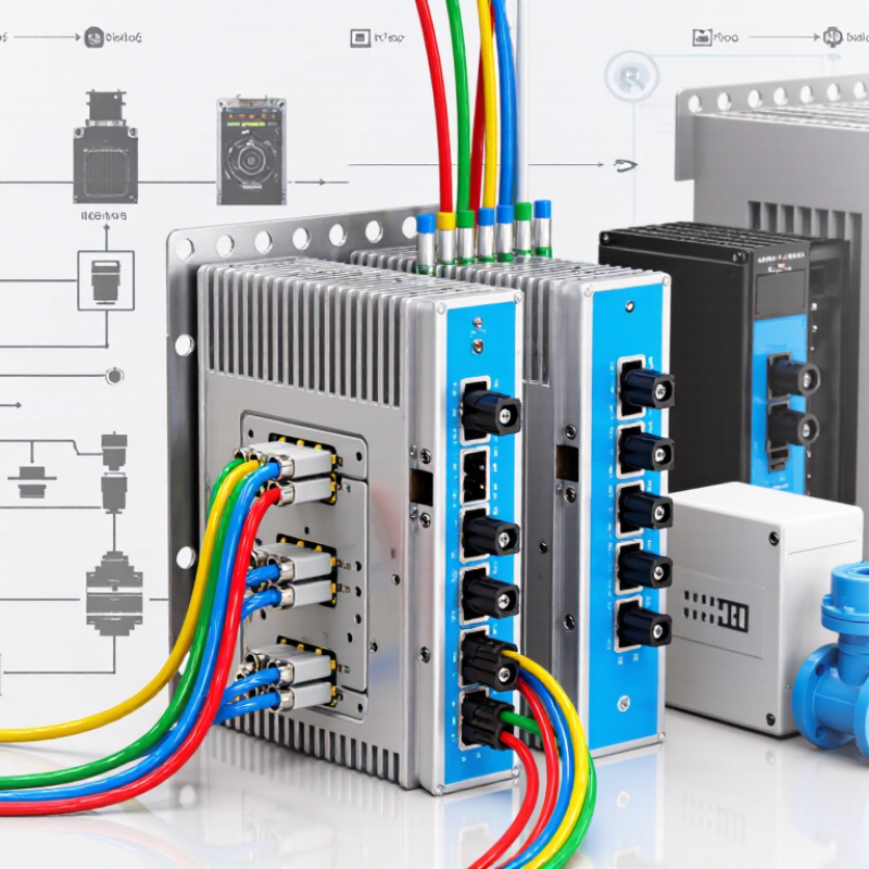
A 4–20 mA analog splitter receives one industrial current signal and creates two or more usable outputs. The input may represent temperature, pressure, flow, or level. For example, 4 mA can indicate an empty tank, while 20 mA represents its configured maximum. The splitter reads this changing current and retransmits proportional signals to separate devices.
Inside the unit, signal-conditioning circuits measure the input without significantly disturbing the control loop. An active splitter uses an external power supply. A passive model draws energy from the loop, so its voltage burden needs careful checking. Galvanic isolation can also separate the input from each output. This helps reduce ground-loop problems and protects connected instruments from some electrical faults. The outputs may be current signals, voltage signals, or different ranges, depending on the design.
During commissioning, I check loop resistance, supply voltage, output accuracy, and terminal polarity before connecting a controller. A splitter with a low stated burden may still fail in a long cable run. That detail matters. Response time, calibration access, enclosure rating, and terminal spacing deserve attention too. I have seen installations overlook output loading because the datasheet appeared clear. A practical test uses a calibrated current source at 4, 12, and 20 mA. Record each output separately. If the application requires independent control systems, choose isolated outputs and verify their accuracy across the expected temperature range. The cheapest option is not always the most dependable.
Define Your Signal and Application Requirements
Choosing the Best Analog Splitter 4 20mA
Define your signal before comparing splitter specifications. Confirm whether the transmitter provides a powered 4–20 mA loop or a passive current signal. Check the input range, output range, supply voltage, and required load resistance. A splitter designed for one signal type may perform poorly with another. Small details matter.
Map the complete application. A control cabinet may need one output for a PLC and another for a display, recorder, or alarm system. Determine whether the outputs must be isolated from each other. Electrical isolation can reduce ground-loop problems and protect sensitive equipment. In a noisy cabinet, this choice becomes important. Very important.
Measure the cable distance and estimate the total loop burden. Long cables and multiple receiving devices can reduce available voltage. Select an accuracy level that matches the process, not simply the most impressive number on a datasheet. Response time, temperature range, mounting method, and terminal access also deserve attention. From practical commissioning work, I have found that unclear wiring notes cause more delays than weak specifications. I once focused too heavily on accuracy and overlooked the power supply margin. That was a useful mistake. Verify the current with a calibrated meter, then test both outputs under normal and fault conditions. A careful field check is still more reliable than assumptions.
Compare Isolation, Accuracy, and Output Configurations
How to Choose the Best Analog Splitter 4 20mA?
When selecting a 4–20 mA analog splitter, compare isolation before price. In control cabinets, electrical isolation can prevent ground loops, protect transmitters, and reduce unstable readings. Check whether the input, output, and power terminals are separately isolated. A unit with two isolated outputs is useful when a PLC and a recorder need the same signal. I have seen installations fail because isolation was assumed, not verified.
Accuracy also needs practical review. Do not examine only the headline percentage. Check temperature drift, response time, load resistance, and calibration tolerance. A splitter may show excellent accuracy at room temperature but drift inside a hot panel. Look for a clear test method in the technical documentation.
Small errors matter when 4 mA represents zero flow. They matter more during long-term dosing control.
Output configuration should match the receiving equipment. Common choices include one input to two current outputs, current plus voltage output, or independently powered channels. Confirm whether the output is active or passive. Also check loop supply limits and maximum burden. A wrong configuration may produce a correct-looking signal that slowly collapses under load.
Tips: Measure the signal at the splitter and the receiver. Record readings at 4, 12, and 20 mA. Test both channels under realistic cable loads. Ask about failure behavior, including open-circuit and over-range conditions. I prefer documented results, although field wiring can still reveal surprises.
Verify Wiring, Power Supply, and Device Compatibility
Choosing the best analog splitter 4-20mA starts with wiring, power supply, and compatibility. A 4-20mA loop carries both signal and fault information. The 2023 NAMUR NE 43 guidance identifies currents below 3.6mA or above 21mA as useful fault indicators. Confirm the splitter preserves this diagnostic range. Check polarity carefully. One reversed terminal can stop the entire loop.
Measure the supply voltage at the splitter terminals, not only at the cabinet. Long cables create voltage loss. For example, a 250-ohm receiving resistor converts 4-20mA into 1-5V. The splitter must still receive enough voltage after sensor, cable, and load resistance are included. IEC 60381-1 specifies the standard current transmission range, but real installations often add unexpected resistance. I have seen apparently correct loops fail during startup because the power margin was too small. Leave practical headroom.
Device compatibility also needs close attention. Verify input type, output isolation, channel count, accuracy, response time, and load capacity. A 2024 industrial automation market report estimated that process industries remain a major demand segment for signal-conditioning equipment, reflecting the need for reliable retrofit solutions. However, market growth does not guarantee universal compatibility. Test the splitter with the actual transmitter and controller. Simulate 4mA, 12mA, and 20mA. Record every output. Small errors can reveal grounding problems or an incorrect power arrangement.
Evaluate Safety, Installation, and Long-Term Reliability
How to Choose the Best Analog Splitter 4 20mA?
Safety starts with signal behavior, not product appearance. Choose a splitter with galvanic isolation between input and outputs. This limits ground-loop currents and protects downstream controllers. Check compliance with IEC 61000-4-2 and IEC 61326-1. These standards address immunity, emissions, and electrical disturbance. Confirm the splitter supports NAMUR NE43 fault signaling. A broken wire should not look like a normal measurement. In hazardous areas, verify the complete installation certificate. A single compatible component is not enough.
Installation details often decide long-term performance. Measure loop burden before connecting field devices. A splitter may need more voltage than expected. Keep signal wiring separate from motor cables and switching conductors. Use shielded cable where interference is likely. Ground the shield at one defined point. During commissioning, record normal current, fault current, cabinet temperature, and terminal torque. This creates useful evidence for future troubleshooting. I have seen loose terminals imitate sensor failure.
Tips: Select removable terminals, clear fault LEDs, and documented HART pass-through behavior. Derate the device near its upper temperature limit. Check isolation voltage, response time, and output accuracy under maximum load. The 2024 Uptime Institute Annual Outage Analysis reported that 54% of serious outages exceeded 100,000 dollars in impact. Its data concerns digital infrastructure, but the lesson applies: small weak points can create expensive downtime. Do not treat MTBF as a guarantee. Verify maintenance access, spare availability, and proof-test procedures before installation.
Article Source:
Submit a quote request or book a design consultation
Plastimold Products is an end-to-end product development and manufacturing team. We provide product design, engineering, prototyping, tooling, plastic injection molding, assembly, packaging and fulfillment. We work with any size company from start-ups to enterprises from all around the world.
I have a product I want to manufacture
I have a product that is already designed and now needs to be manufactured.
I need a manufacturer to optimize my product for injection molding, help choose the correct material, and manage the product production.
I have tooling that I want to transfer or modify, or I need to produce new tooling.
I need design and engineering support
I have a product concept that I want to be designed and brought to market.
I have a product that needs to be reviewed, improved or DFM’ed.
I am looking for a manufacturer to provide an end-to-end solution, from design and development to inventory, marketing, and sales.

©2022 Plastimold Products - Privacy policy - Terms and Conditions

